

Higgstec T057S-5RB006N-0A11R1-080PN Touch Screen Panel
group nameHiggstec Touch Panel
-
Min Order1 piece
brand nameVICPAS
modelT057S-5RB006N-0A11R1-080PN
payment methodWestern Union, MoneyGram, T/T, Paypal, PayPal
-
update timeSat, 01 Jun 2024 12:21:51 GMT
Paramtents
Warranty 365 Days
Shipping DHL/FedEx/UPS/TNT/EMS/Aramex /DPEX
Touch points Single-touch
Place of Origin China
HMI touch glass touch digitizer glass
HMI panel glass touch screen monitor
Name T057S-5RB006N-0A11R1-080PN Touch Screen Panel
Packging & Delivery
Weight0.50kg / piece
Min Order1 piece
Briefing
Detailed
Higgstec T057S-5RB006N-0A11R1-080PN Touch Screen Panel
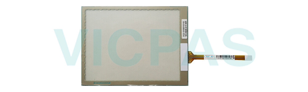
T057S-5RB006N-0A11R1-080PN touch screen
T057S-5RB006N-0A11R1-080PN touch panel
T057S-5RB006N-0A11R1-080PN touch membrane
T057S-5RB006N-0A11R1-080PN touch glass
T057S-5RB006N-0A11R1-080PN touch digitizer
T057S-5RB006N-0A11R1-080PN HMI touch glass
T057S-5RB006N-0A11R1-080PN Touchscreen
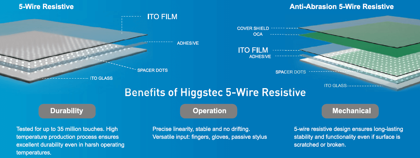
5-Wire Resistive Touch Solution
Extremely stable, reliable and immune to electromagnetic interference, resistive touch technology remains popular today for critical applications such as for medical, aerospace and military use. Higgstec specializes in production of 5-Wire Resistive technology because of its superior endurance and reliability. 5-wire resistive screens don't require repeated calibration and can continue to function even when the surface has been scratched or damaged, because both the X and Y axis are detected on the lower (glass) layer, while the upper (film) layer is used as loop conduction only
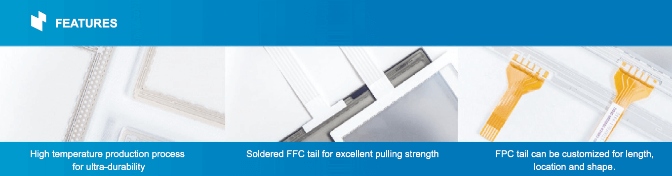
Higgstec also uses a special high temperature production process for its resistive screens to fuse the silver sensor circuit onto the glass, preventing it from peeling off during extreme temperature or humidity variations, ensuring greater longevity and durability in harsh operating environments
A front cover shield (glass, fiberglass, PMMA or other material) can also be added to the front of the resistive panel for anti-abrasion and chemical resistance protection.
FAQ:
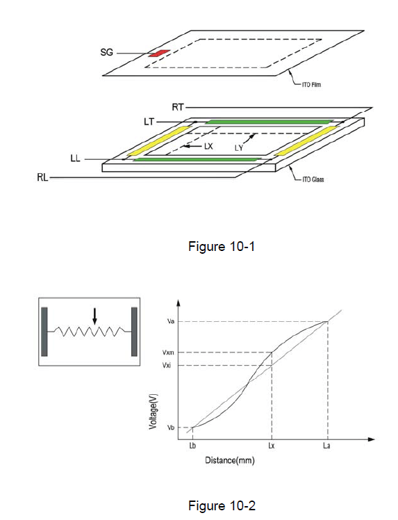
Question: Inspection Methods:
Answer:
Linearity Condition
Step 1: short RT and RL(or short RL and LL).
Step 2: apply voltage DC 5V.
Step 3: short LT and LL (or short RT and LT).
Step 4: apply grounding.
Step 5: draw points along LX and LY at 5.0mm intervals within
pattern area and detect the voltage at SG.
Step 6: measure the voltage differences between RT and LT
(or RT and RL) (Fig 10-1) (Fig 10-2)
You need a product


You May Like


- Nearest port for product export
- Guangzhou, Shenzhen, Hongkong, TaiWan
- Delivery clauses under the trade mode
- FOB, CFR, EXW, CPT, DDU, Express Delivery
- Acceptable payment methods
- T/T, L/C, MoneyGram, Credit Card, PayPal, Westem Union, Cash, Escrow
- Export mode
- Export through agents