


Boat Rubber Pneumatic Yokohama Type Marine Fenders
group nameCNT Pneumatic Rubber Fender
-
Min Order1 piece
brand nameJerryborg Marine,safe docking,safe mooring
modelJRBM-01
payment methodL/C, D/A, D/P, Western Union, MoneyGram, T/T, Paypal
-
update timeMon, 30 Nov 2020 10:10:02 GMT
Paramtents
Product Name Pneumatic fender
Material nature rubber
Model JRB-PF-01
Fender Diameter 0.5-4.5 meters
Fender Length 1.0-9.0 meters
Standard ISO: 17357-2014
Place of Origin Qingdao , China
Packging & Delivery
Min Order1 piece
Briefing
Detailed
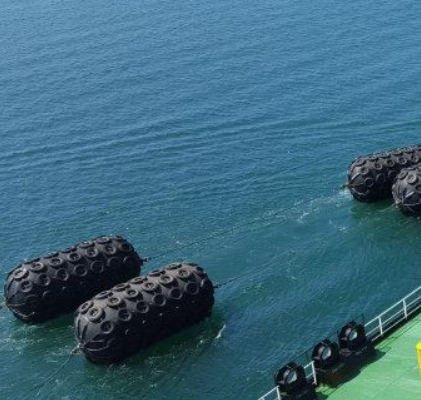
The marine fender was developed in 1958 in Japan. The marine fenders should be manufactured according to ISO 17357. The standard defines the corresponding international standards for the materials and testing of these fenders. In most cases, marine fenders should be surrounded by a tire and chain net for additional protection.
Marine fenders are extensively used for ship-to-ship (STS) transfer operations, terminals, and for all kinds of ships, large tankers, vessels, docks, harbor wharves and ocean platforms.
Nominal Size diameter × length mm | Initial internal pressure kPa | Guaranteed energy absorption (GEA) | Reaction force at GEA deflection (R) | Hull pressure (Internal pressure) at GEA deflection (P) |
Minimum value at deflection 60 ± 5 % kJ | Tolerance ±10 % kN | Reference value kPa | ||
500 × 1 000 | 50 | 6 | 64 | 132 |
600 × 1 000 | 50 | 8 | 74 | 126 |
700 × 1 500 | 50 | 17 | 137 | 135 |
1 000 × 1 500 | 50 | 32 | 182 | 122 |
1 000 × 2 000 | 50 | 45 | 257 | 132 |
1 200 × 2 000 | 50 | 63 | 297 | 126 |
1 350 × 2 500 | 50 | 102 | 427 | 130 |
1 500 × 3 000 | 50 | 153 | 579 | 132 |
1 700 × 3 000 | 50 | 191 | 639 | 128 |
2 000 × 3 500 | 50 | 308 | 875 | 128 |
2 500 × 4 000 | 50 | 663 | 1381 | 137 |
2 500 × 5 500 | 50 | 943 | 2019 | 148 |
3 300 × 4 500 | 50 | 1175 | 1884 | 130 |
3 300 × 6 500 | 50 | 1814 | 3015 | 146 |
3 300 × 10 600 | 50 | 3067 | 5257 | 158 |
4 500 × 9 000 | 50 | 4752 | 5747 | 146 |
4 500 × 12 000 | 50 | 6473 | 7984 | 154 |
Nominal size diameter × length mm | Initial internal pressure kPa | Guaranteed energy absorption (GEA) | Reaction force at GEA deflection (R) | Hull pressure (Internal pressure) at GEA deflection (P) |
Minimum value at deflection 60 ± 5 % kJ | Tolerance ±10 % kN | Reference value kPa | ||
500 × 1 000 | 80 | 8 | 85 | 174 |
600 × 1 000 | 80 | 11 | 98 | 166 |
700 × 1 500 | 80 | 24 | 180 | 177 |
1 000 × 1 500 | 80 | 45 | 239 | 160 |
1 000 × 2 000 | 80 | 63 | 338 | 174 |
1 200 × 2 000 | 80 | 88 | 390 | 166 |
1 350 × 2 500 | 80 | 142 | 561 | 170 |
1 500 × 3 000 | 80 | 214 | 761 | 174 |
1 700 × 3 000 | 80 | 267 | 840 | 168 |
2 000 × 3 500 | 80 | 430 | 1150 | 168 |
2 500 × 4 000 | 80 | 925 | 1815 | 180 |
2 500 × 5 500 | 80 | 1317 | 2653 | 195 |
3 300 × 4 500 | 80 | 1640 | 2476 | 171 |
3 300 × 6 500 | 80 | 2532 | 3961 | 191 |
3 300 × 10 600 | 80 | 4281 | 6907 | 208 |
4 500 × 9 000 | 80 | 6633 | 7551 | 192 |
4 500 × 12 000 | 80 | 9037 | 10490 | 202 |
You need a product


You May Like


- Nearest port for product export
- Qingdao Port, Shanghai Port
- Delivery clauses under the trade mode
- FOB, CFR, CIF, EXW, DDP, DDU, Express Delivery
- Acceptable payment methods
- T/T, L/C, D/P D/A, MoneyGram, Credit Card, PayPal, Westem Union, Cash