TY 24 core mini cable air blown micro fiber optic cable")


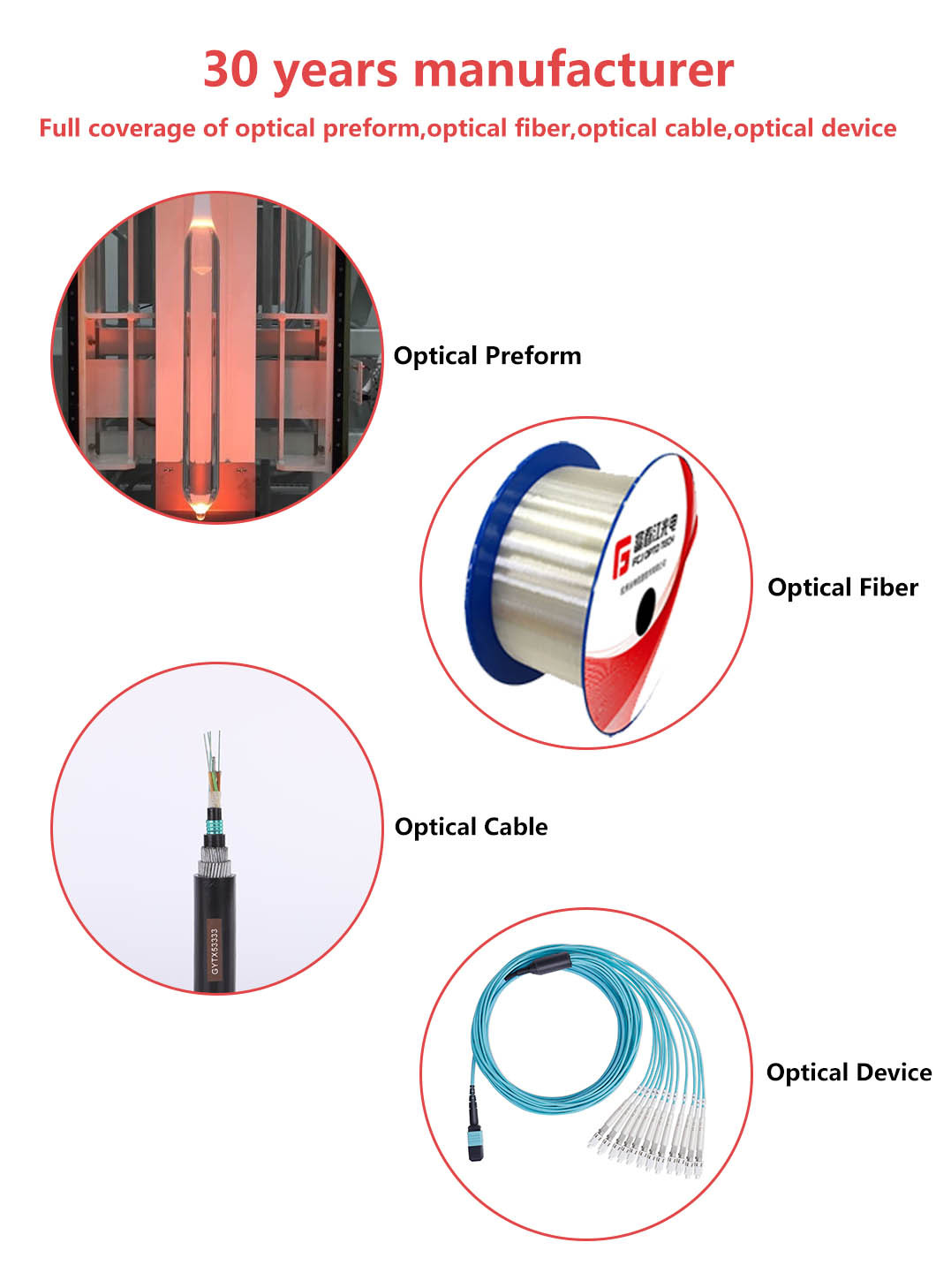
FCJ factory China manufacturer GCYF(X)TY 24 core mini cable air blown micro fiber optic cable
group nameMicro Air Blown Fiber Optic Cables
-
Min Order1 kilometer
brand nameFCJ Fiber Optic Products Manufacturer
modelGCYF(X)TY
payment methodL/C, D/A, D/P, Western Union, T/T, Paypal
-
update timeWed, 27 Sep 2023 10:35:56 GMT
Paramtents
Number of Cores 2~24
Fiber Type G652D/Multimode
Armored Yes
Operating Temperature -40°C to + 70°C
Installation Duct
Transport Package Wooden Drums or as Per Customers′ Requests
Packging & Delivery
Min Order1 kilometer
Briefing
Detailed
1. General
This specification covers the design and performance of the single mode optical cables to be used in air blown micro duct application.
1.1 Cable Description
Ÿ Ÿ2/4/6/8/12/24 G657A1 SM-fibers..
Ÿ Ÿ Central tube structure
Ÿ ŸSuitable for air blown cable in micro-duct installation.
1.2 Quality
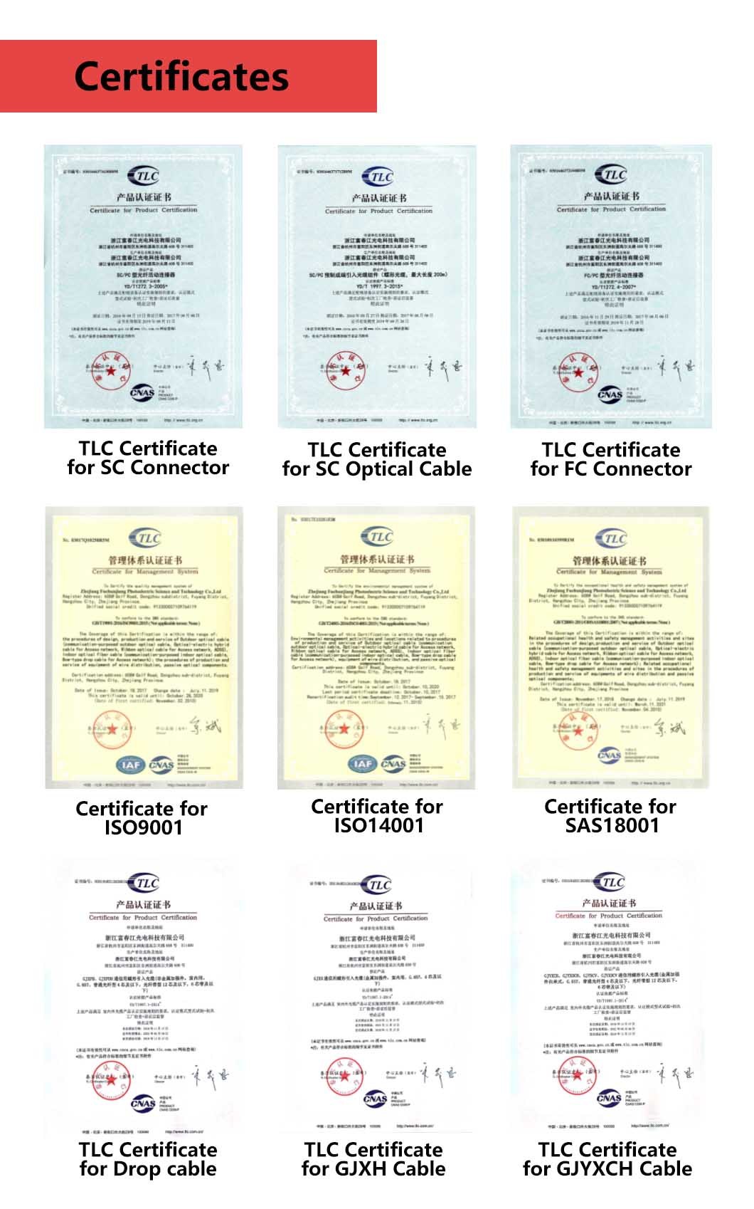
FCJ GROUP ensures a continuing level of quality in our cable products through several programs including ISO 9001.
1.3 Reliability
FCJ GROUP ensures product reliability through rigorous qualification testing of each product family. Both initial and periodic qualification testing are performed to assure the cable’s performance and durability in the field environment.
1.4 Reference
ITU-T G.657.A1 | Characteristics of a single-mode optical fiber |
IEC 60794-1-1 | Optical fiber cables- part1-1-Generic specification-General |
IEC 60794-1-2 | Optical fiber cables- part1-2-Generic specification-Basic optical cable test procedure |
IEC 60794-3 | Optical fiber cables- part3-Sectional specification- Outdoor cables |
IEC 60794-5 | Optical fiber cables- part5-Sectional specification- Microduct cabling for installation by blowing |
1.5 Working Condition
Transportation and storage temperature:-40℃~+70℃
Installation temperature: -5℃~+60℃
Operation temperature: -20℃~+70℃
1.6 Minimum Allowable Bending Radius
Static: 10D
Dynamic: 20D
D is the out diameter of the cable
1.7 Life Time
Optical fiber cables supplied in compliance with the specifications can be capable of withstanding the typical service condition for a period of twenty-five (25) years without detriment to the transmission or operation and maintenance characteristics of the cable.
2. Optical Fiber In Cable(ITU-G657A1)
Optical properties of the SM fiber are achieved through a germanium doped silica based core with a pure silica cladding which meets ITU-T G657A1, UV curable acrylate protective coating is applied over the glass cladding to provide the necessary maximum fiber lifetime.
Geometrical, optical, and mechanical characteristics of fiber in cable as the following table:
Specification | |||
Before cable | After cable | ||
1310 nm | £ 0.35 dB/km | £ 0.36 dB/km | |
1383 nm | £ 0.35 dB/km | £ 0.36 dB/km | |
1550 nm | £ 0.25 dB/km | £ 0.25 dB/km | |
1625 nm | £ 0.25 dB/km | £ 0.25 dB/km | |
Dispersion coefficient | 1285 – 1340 nm | ≥-3.4 £ 3.4 ps/(nm·km) | |
1550 nm | £ 18 ps/(nm·km) | ||
1625 nm | £ 22 ps/(nm·km) | ||
Zero dispersion wavelength |
| 1300 – 1324 nm | |
Zero dispersion slope |
| £ 0.091 ps/(nm2·km) | |
Cable cut-off wavelength |
| £ 1260 nm | |
Polarization mode dispersion | individual fibre | £ 0.15 ps/Ökm | |
design link value (M=20, Q=0.01%) | £ 0.1 ps/Ökm | ||
Mode field diameter | 1310nm | 8.4~9.2 mm | |
1550nm | 10.4 ± 0.5 mm | ||
Cladding diameter |
| 125.0 ± 0.7 mm | |
Cladding non-circularity |
| £ 1.0 % | |
Core concentricity error |
| £ 0.6mm | |
Coating diameter |
| 245± 10 mm(Before Colored) 250 ± 15 mm (Colored) | |
Coating/cladding concentricity error |
| £ 12mm | |
Proof stress level |
| ³100kpsi (0.69 GPa) | |
Coating strip force(peak value) |
| 1.3~8.9N | |
Macro bend induced attenuation | 10 turns around 15mm radius @ 1550nm | £0.25
| |
10 turns around 15mm radius @ 1625nm | £1.0
| ||
1 turn around 10mm radius @ 1550nm | £0.75
| ||
1 turn around 10mm radius @ 1625nm | £1.5 | ||
3. Optic Cable
3.1 General Design
Optical fibers are housed in central loose tube that is made of high-modulus plastic and filled with waterproof compounds.
Polyethylene sheath is applied over the cable core.
3.2 Construction
3.2.1 Cross Section of Cable

3.2.2 Dimensions and Descriptions of Cable Constructions
Item | Contents | Value | |||||
Fiber | number | 2 | 4 | 6 | 8 | 12 | 24 |
Loose tube | diameter(±0.2mm) | 2.0 | 3.0 | ||||
Outer sheath | Material | HDPE | HDPE | ||||
Color | Black | Black | |||||
Thickness(mm) | Approx.0.3 | Approx.0.3 | |||||
Cable diameter(mm) Approx | 2.5±0.1 | 3.7±0.1 | |||||
Cable weight(kg/km) Approx. | 5 | 11 | |||||
3.2.3 Mechanical Performance of Cable
Tensile performance(N) | Crush(N/100mm) | ||
Short term | Long term | Short term | Long term |
1.0G | 0.5G | 500 | 150 |
“G” is the weight of cable per kilometer, the unit is Newton (N).
3.2.4 Color Code of the Fiber
Each fiber can be identifiable throughout the length of the cable in accordance with the following color sequence. Fiber color in each tube starts from No. 1 Blue.
Fiber color code | 12 fibers per tube | 1 | 2 | 3 | 4 | 5 | 6 | ||||
Blue | Orange | Green | Brown | Slate | White | ||||||
7 | 8 | 9 | 10 | 11 | 12 | ||||||
Red | Black | Yellow | Purple | Pink | Aqua | ||||||
24 fibers per tube | 1 | 2 | 3 | 4 | 5 | 6 | |||||
Blue | Orange | Green | Brown | Slate | White | ||||||
7 | 8 | 9 | 10 | 11 | 12 | ||||||
Red | Black | Yellow | Purple | Pink | Aqua | ||||||
13 | 14 | 15 | 16 | 17 | 18 | ||||||
Blue with black ring | Orange with black ring | Green with black ring | Brown with black ring | Slate with black ring | White with black ring | ||||||
19 | 20 | 21 | 22 | 23 | 24 | ||||||
Red with black ring | Nature
| Yellow with black ring | Purple with black ring | Pink with black ring | Aqua with black ring | ||||||
Notes: No.13-24 fibers with black ring except the black fiber which is nature color in stead
3.2.5 Color Code of the Loose Tube and Filler
The color of the tube will be YELLOW.
3.3Mechanical, Electrical and Environmental Test Characteristics
The finished cables can be subjected to the following mechanical, electrical and environmental conditions.
Item | Test Method | Requirements |
Tensile performance | IEC 60794-1-2-E1 Load: 1.0G*W Cable length under tension: Not less than 50m. Duration of load sustain: 1min. Velocity of transfer device: 10mm/min
| The maximum increase in attenuation less than 0.1 dB . No change in attenuation after test at 1550nm. Under visual examination without magnification, no damage to the sheath or to the cable elements after test.
|
Crush | IEC 60794-1-2-E3 Load: 500N Duration of load: 1min
| No change in attenuation after test at 1550nm. Under visual examination without magnification, no damage to the sheath or to the cable elements. The imprint of the striking surface on the sheath is not considered mechanical damage. |
Bend | IEC 60794-1-2-E11A Mandrel radius: 10 times cable diameter Turns:10 Cycles:5
| No change in attenuation at 1550nm after test.Under visual examination without magnification, no damage to the sheath or to the cable elements. |
Repeated bending | IEC 60794-1-2-E6 Bending radius: 20 times cable diameter Cycles: 25 Load: 25N Duration of cycle: Approximately 2s. | No change in attenuation at 1550nm after test. Under visual examination without magnification, no damage to the sheath or to the cable elements.
|
Torsion | IEC 60794-1-2-E7 Cycles:5 Length under test: 1m Turns: ±180° Load: 1.0G*W
| The variation on attenuation for each fiber less than 0.1dB at 1550nm Under visual examination without magnification, no damage to the sheath or to the cable elements. No permanent change in attenuation after test |
Temperature cycling | IEC 60794-1-2-F1 Sample length: at least 1000m Temperature range: -20℃~+70℃ Cycles: 2 Temperature cycling test dwell time: 12 hours | No change in attenuation coefficient at 1550nm after test.
|
Water Penetration | IEC 60794-1-2-F5B Time : 24 hours Sample length : 3m Water height : 1m
| No water leakage
|
Compound flow | IEC 60794-1-2-E14 Sample count:5 Sample length:300 ±5 mm, Remove length: 130 ±2.5 mm, Time:24h
| No filling compound dripped.
|
Other parameters | According to IEC 60794 | |
Remark: “No attenuation changes” is considered as the attenuation changes ≤ 0.05 dB.
4. Cable Sheath Marking
Unless otherwise specified, the cable sheath marking shall be as follows:
Ø Color: white
Ø Contents: FCJ GROUP, the year of manufacture, the type of cable, length marking
Ø Interval: 1m
5. Packaging and Shipping
5.1 Reel Length
Standard reel length: 2/4/6 km/reel
5.2 Cable Drum
The cables are packed in wooden drums
The minimum barrel diameter of the drum shall be more than 30 times of the nominal diameter for armored cable, and 25 times of the nominal diameter for unarmored cable.
5.3 Labeling
The direction of rotation of the color scheme is shown by marking the clockwise and anti-clockwise ends with red and green adhesive tape respectively.
The markings are on both sides of the flanges as follows:
Ø Cable Type/Size
Ø Cable Length
Ø Gross Weight.
Ø FCJ GROUP.
Ø Shipping mark.
5.4 Cable Packing
Both cable ends are provided with protections against water penetration and firmly secured to the drum, so the cable cannot move and the turns cannot slide when it is moved, handled or laid. the inner end has at least 3 meters of accessible length to perform reception tests in the cables.
You need a product


TY 24 core mini cable air blown micro fiber optic cable")

You May Like


TY 24 core mini cable air blown micro fiber optic cable")

6YRS FCJ OPTO TECH
- Nearest port for product export
- shanghai, Ningbo, Shenzhen, Guangzhou
- Delivery clauses under the trade mode
- FOB, CIF, EXW, Express Delivery
- Acceptable payment methods
- T/T, L/C, Credit Card, PayPal, Westem Union